About This Workshop ▶
Brief History of Op-Amp Usage and Significance
▶ Watch: Brief History of Op-Amp Usage (10:07)
▶ Watch: Op-Amp Basics (5:11)
Modern processors and electronics typically use 0..5V supply voltages, which imposes certain limitations on amplifier circuits and components. Op-amp amplifiers are supplied with 0..5V single-ended power, so negative signals cannot be used. This significantly limits available circuit configurations compared to traditional ±15V dual-supply systems.
The operational amplifier (op-amp) has been and remains a fundamental electronic component, especially in embedded systems (such as Arduino). It has played a crucial role in the design and implementation of analog computers and many other technical devices. Today, however, many functions that previously required op-amps can be replaced by small computers.
Therefore, this workshop focuses on a few circuit configurations that still have great practical significance. The key concept is how to obtain signals from various sensors (typically in the 0..5V or 0..3.3V range) that the processor's ADC (analog-to-digital converter) can read. We concentrate on circuits needed around the Arduino development environment, focusing primarily on analog DC signals, while AC signals and audio applications are excluded from the scope.
Introduction to New Tools
This workshop also introduces new tools for circuit analysis: the oscilloscope and the 555 signal generator. Additionally, we will explore RLC circuit analysis, which provides fundamental understanding of reactive components and their behavior in electronic circuits.
▶ 555 Timer Circuit
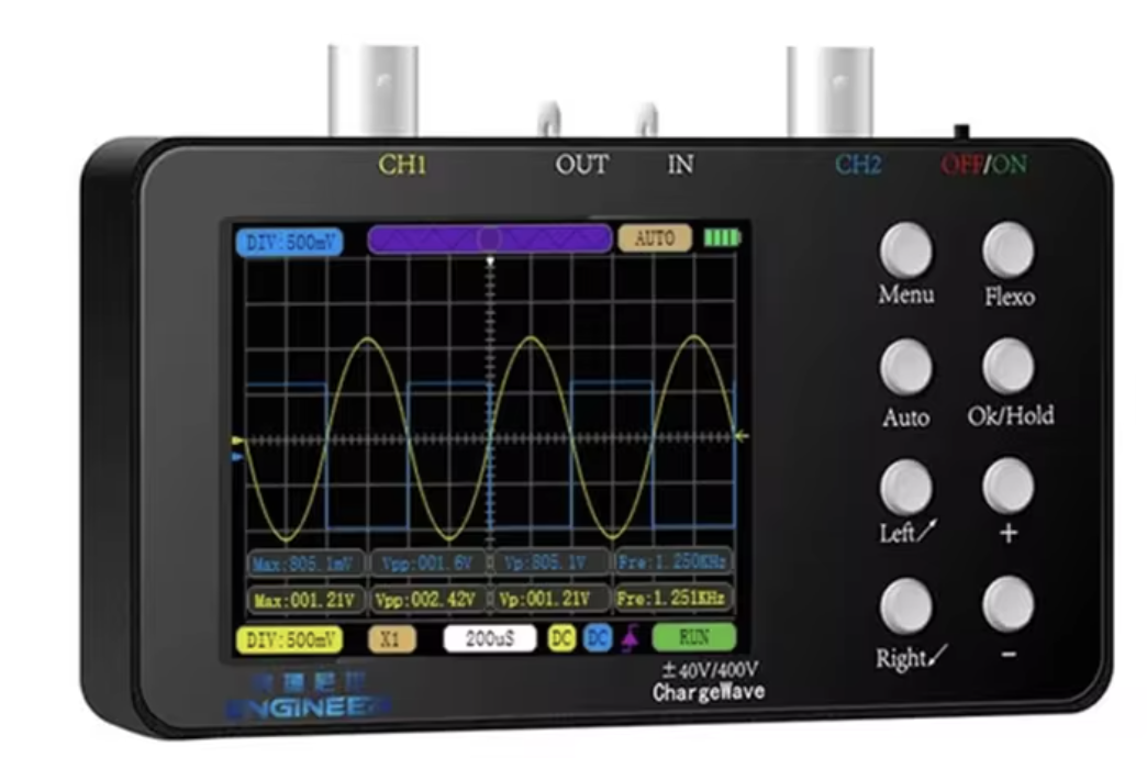
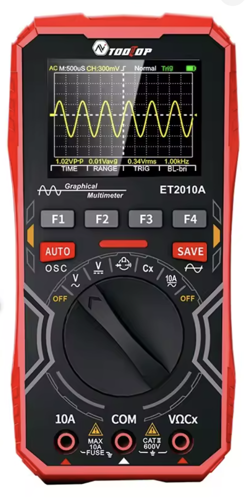
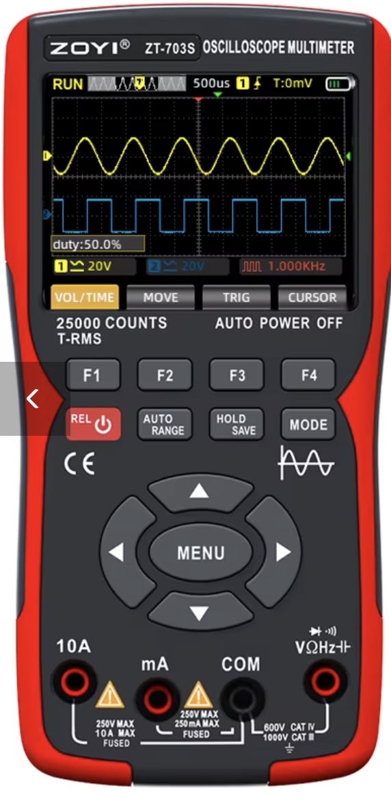
▶ Affordable Portable Oscilloscope and Usage
▶ YouTube - EasyEDA Tutorial for Beginners
▶ YouTube - EasyEDA Tutorial for Beginners
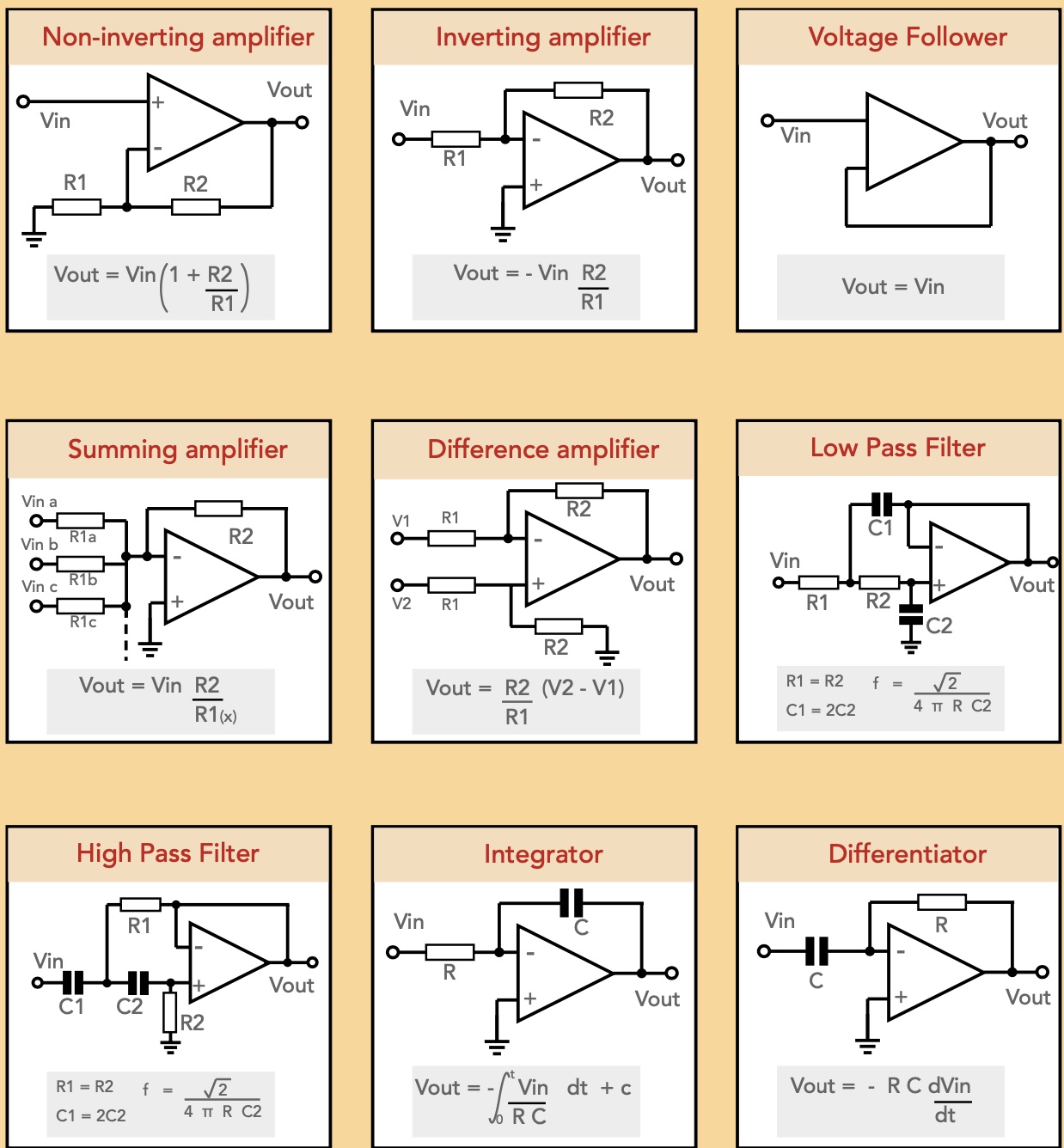
This workshop covers the following op-amp circuits:
- Voltage follower
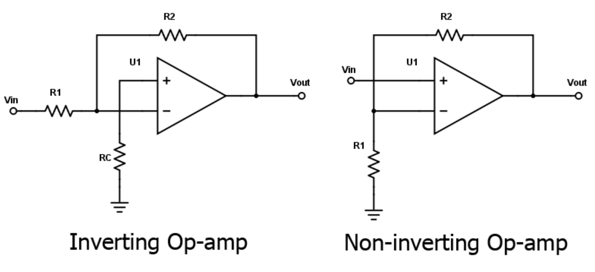
- Inverting and non-inverting amplifier
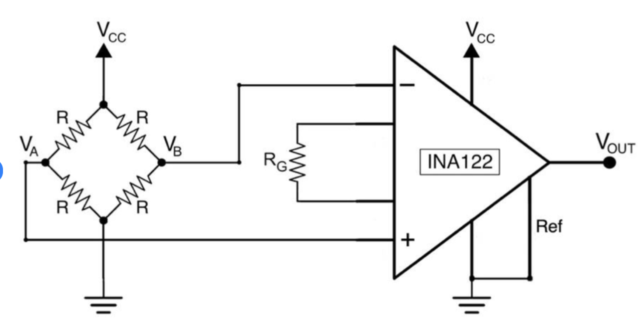
- Amplification + level shifting
- Various active filters
Testing the 555 Timer Circuit and Oscilloscope
Task: Learning to use an oscilloscope and investigating voltage boost circuit operation with it
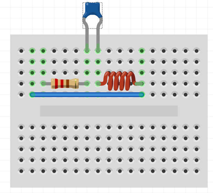
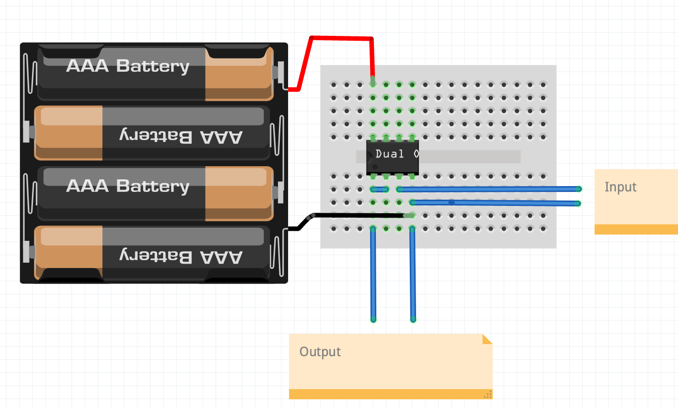
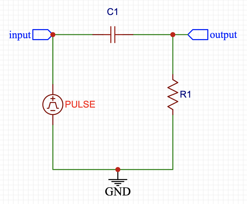
First of all, the purpose is to investigate resonance as a phenomenon. The first image is just the idea of the circuit. That is, we do not have information about the values of individual components (C and L), but we know that this connection is an oscillating circuit. However, we have at our disposal a small oscilloscope, components, and a small 555 circuit that gives us a square wave. The purpose of this first task is to find the frequency at which the circuit begins to oscillate.
Below are images of a signal generator (555-based) and various oscilloscopes that come with the course materials. By clicking on the images, you can access YouTube instructions.
⚠️ Warning: Do not connect to mains power, but test the 555 pulse generator.
Tip: Press the AUTO button.