- Part 1: Basic components
- Resistor
- Task 1: Measure resistor value (Ohm)
- Task 2: LED Connection
- Task 3: LED + Potentiometer
- Task 4: Current Measurement
- Task 5: Potentiometer
- Task 6: Voltage Divider
- Task 7: LDR (Light Sensor)
- Task 8: Light to Voltage
- Task 9: Capacitor
- Task 10: Diode
- Task 11: Regulator 7805
- Task 12: Transistor
- Task 15: Seven Segment LED
- Task 16: RGB LED
- Task 17: Buzzer
- Task 18: Soldering
- Task 19: What is Pull-up Resistor?
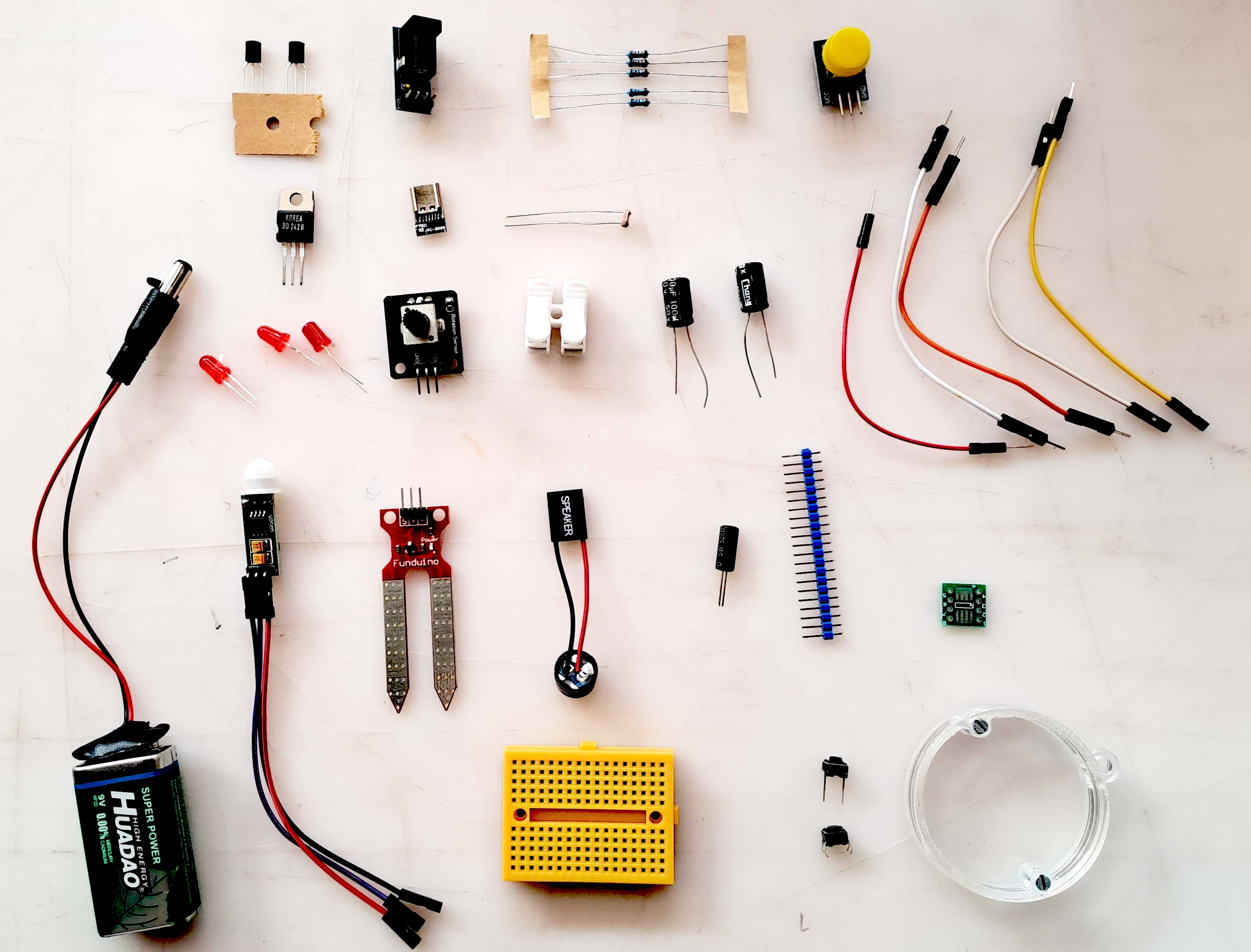
Part 1: Basic components
Goal: Learn how electricity flows in a circuit and how passive components work together.
▶ Watch: Basic Electronics Introduction (YouTube)
Basic Analog Circuits
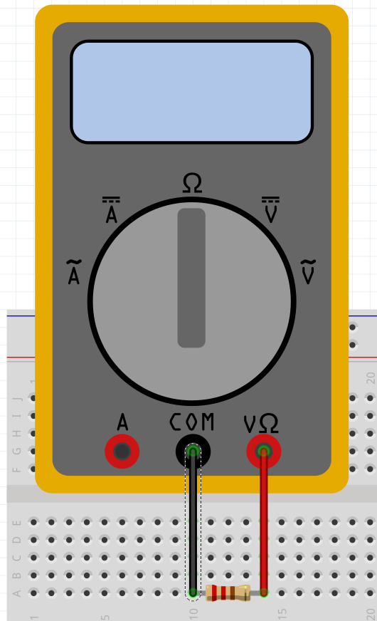
Task 1: Measure resistor value (Ohm)
Note: Check that you have connected the test leads correctly: COM (black) and Ohm symbol (red). Often the resistance range must also be selected correctly, as resistors vary from 0.01 ohms to megaohms.
For our workshops, the essential values are approximately 100 ohms (for protecting LEDs) and later approximately 1000 ohms (for controlling transistors).
The value of small resistors can also be estimated based on the color code. Resistor Color Code Calculator
Task: Find a resistor of approximately 100-200 ohms. You will need it in the next LED circuit.
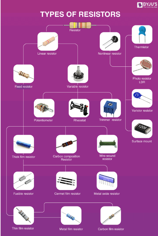
Resistor
The purpose of a resistor is to limit current. There are two main types of resistors: SMD (surface-mount device) and through-hole. The image shows different types of resistors, and the smallest ones, known as carbon film resistors, often have a color code to identify their resistance value.
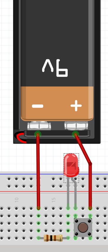
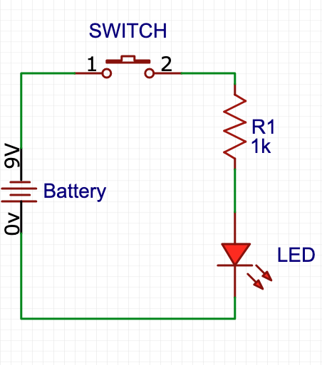
Task 2: LED Connection
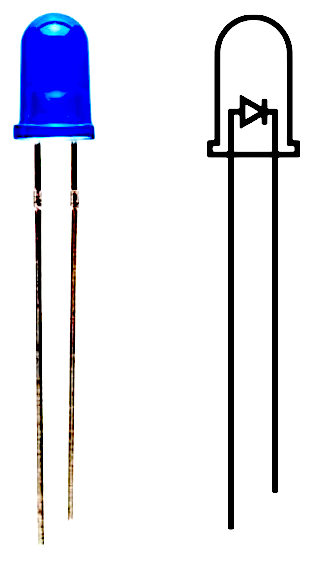
LED (Light Emitting Diode) must be connected with correct polarity. See the image: the longer leg of the LED is connected to the positive side (+).
LED almost always needs a protective resistor. As a rule of thumb, approximately 400 ohms. The resistor can be on either side of the LED.
More precisely, the resistor size can be calculated on this page: LED Calculator. It is essential to know how much current the LED can handle, usually 20mA (milliAmp).
The LED will not light up if the voltage is not above the threshold. Make the connection and try it out. You will also need a switch. Be careful that the switch is connected correctly.
Common mistakes:
- Switch connected incorrectly
- Resistor too large
- LED connected incorrectly (long leg should be +)
- Rule of thumb: if the LED feels hot on your thumb, something is wrong
YouTube Videos
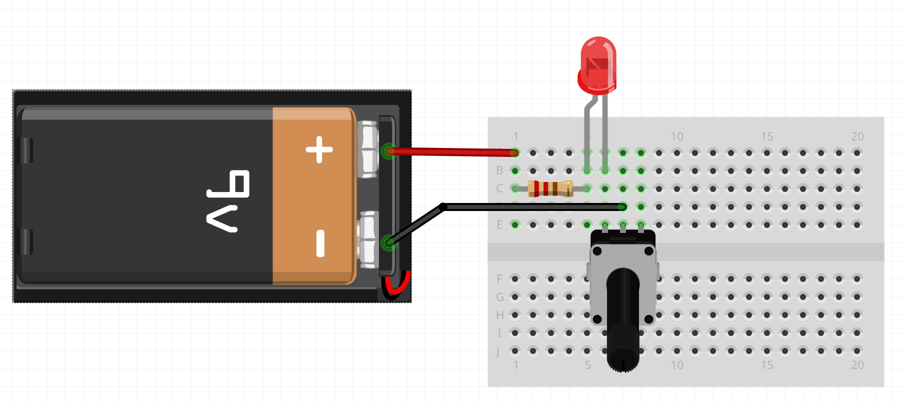
Task 3: LED + Potentiometer
You can change the brightness of the LED by adjusting the potentiometer value between 0 and maximum resistance.
Important: It is essential to place a resistor before the potentiometer, in case the potentiometer resistance goes to zero. In this case, the LED would receive too much current and could be damaged.
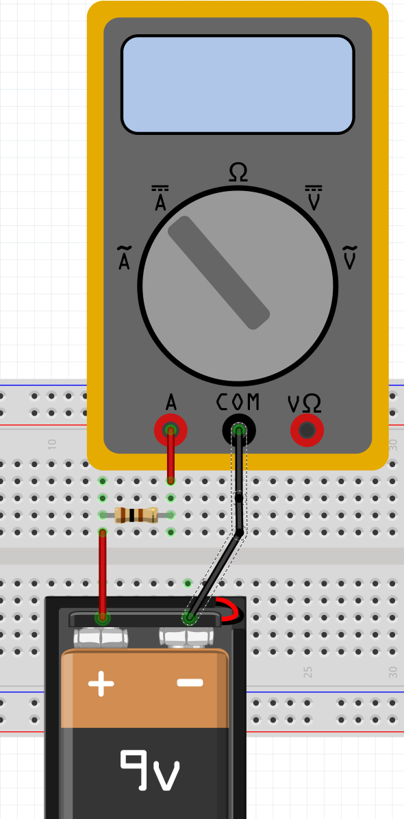
Task 4: Current Measurement
Switch the meter probes to the correct place, i.e. to amperes (A). Note that current measurement often has two different places: for large currents and small currents. If you measure large current with the wrong pin, the meter's internal resistor usually burns out. So you must be careful.
Similarly, meters often have separate position switches for alternating current (AC ~) and direct current (DC ⎓). See the image for how they are marked.
Note: If current flows in the opposite direction, the meter will show a negative value.
Task: You have already found a resistor with a value of approximately 100 ohms. Calculate first what the current should be, and then check with the meter if you got the same value.
Ohm's Law Calculator
Current (I): 90.00 mA
Task 5: Potentiometer
A potentiometer is a three-terminal variable resistor. By rotating the shaft, you can change the resistance between the terminals. Potentiometers are commonly used for volume controls, light dimmers, and other adjustable settings.
Learn more: Wikipedia - Potentiometer
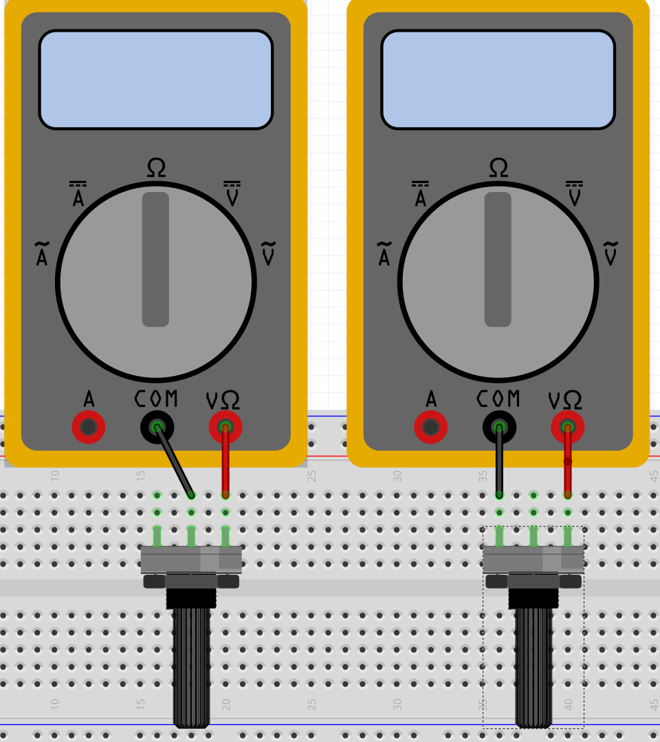
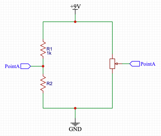
Task: Take random two resistance R1 and R2. Put them in breadboard as following picture shows. Adjust the pot value so that point A and B have at same voltage. So voltage difference between A and B is zero. Can you determine the resistor 1 and 2?
Can you determine the ratio of R1 and R2 from potentiometer?

Task 6: Voltage Divider
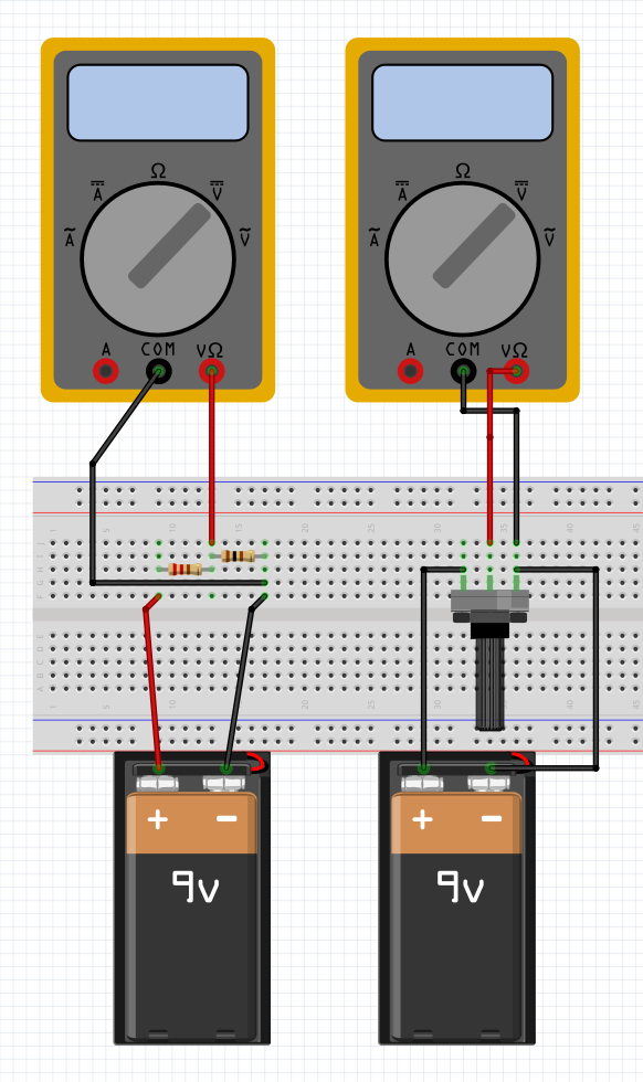
Voltage division is needed in many circuits, and especially in the future when you start Arduino programming. The basic idea of a voltage divider is shown in the image on the left.
Select DC voltage on the multimeter and make the connections shown in the image. Use two resistors (both approximately 1000 ohms).
Note: If you get a negative value for voltage, it means that the current direction is opposite to what you assumed. Electricity flows from higher potential to lower potential, just like water, so switch the measurement probe positions.
Voltage Divider Calculator
Output Voltage: 4.50 V
Task 7: LDR (Light Sensor)
We have many sensors whose resistance changes due to the amount of light, temperature, strain, etc. For example, a light sensor's resistance can change according to the amount of light, a temperature sensor's resistance increases or decreases according to temperature, etc.
In this context, you can test for example a light sensor and its resistance. In the next task, we will convert the light sensor's resistance change into a voltage change. This is needed later in Arduino programming, as the Arduino platform can read voltage values.

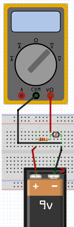
Task 8: Light to Voltage
Depending on the characteristics of the light sensor/temperature sensor, the resistor value must be adjusted. There are also better circuits that can extend the measurement range. Remember to switch the multimeter setting to voltage!
For some sensors, the resistance change is so small that a simple voltage divider is not enough. In such cases, different circuits and amplifiers are needed. These will be covered in future workshops.
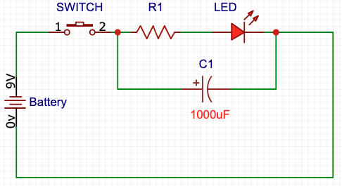
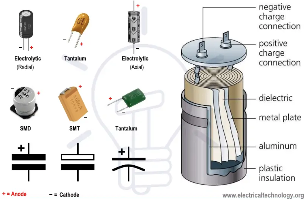
Task 9: Capacitor
In this exercise, we consider capacitors as "buckets of charge". The most common polarized capacitor is the electrolytic capacitor (elko). For elkos, the longer leg is positive (+) and the shorter leg is negative (-). This polarity is especially important when dealing with higher voltages, as incorrect connection can cause the capacitor to explode or leak.
Try the LED circuit in your breadboard with a large capacitor (see circuit diagram on the left) and see how it corresponds to the calculator below.
Usually capacitors are not precisely dimensioned (there are exceptions, of course), but rather sufficient capacitance is stocked to smooth out load variations. Capacitors can also age and dry out, especially electrolytic capacitors (cans), and their placement must be careful - not near hot components. Capacitance also changes strongly with temperature changes. More precise capacitance dimensioning will be covered later.
Additional Resources
- YouTube - Capacitor Charging and Discharging
- YouTube - Electrolytic Capacitor Wrong Polarity Effects
- Electronics Tutorials - Capacitors
Charge Calculator
Charge: 9000 µC
Time Constant Calculator
τ: 1000 ms
LED Time Calculator
Time: 1633 ms

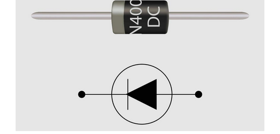
Task 10: Diode
A diode is a semiconductor device that allows current to flow in one direction only. It acts like a one-way valve for electric current. Current flows easily in the forward direction (anode to cathode), but is blocked in the reverse direction. Diodes require a minimum forward voltage to conduct (typically 0.7V for silicon diodes).
Diodes are used in many applications such as rectifiers, crystal radios, power supplies to prevent wrong polarity (plus and minus voltage), they even work as thermometers, etc.
To Do
- Measure voltage drop alongside diode
- Test if diode is working
- Test to simulate diode in simulator: Falstad Circuit Simulator
Additional Resources
Task 11: Regulator 7805
The 7805 is a 5V voltage regulator. It takes an input voltage (7-35V) and provides a stable 5V output. This is very useful when you need a consistent 5V supply for circuits.
To Do
- Build basic voltage regulator using 7805
- Measure input and output voltages
- Try voltage regulator in Tinkercad: Tinkercad
7805 Regulator Power Calculator
Power dissipation: 0.70 W


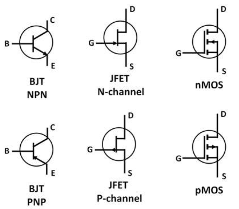
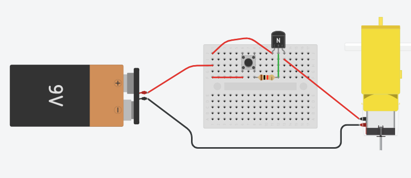
Task 12: Transistor
Advanced topic.
The basic idea of a transistor is to control high power with very small power. Power is calculated with the formula: P = U × I
There are two basic types of transistors: current-controlled (BJT) and voltage-controlled (FET). The exercise shown in the top image is for a current-controlled BJT type transistor (NPN). Below that is a voltage-controlled transistor (FET).
Note that all transistors have different characteristics and pin arrangements. However, the principle is the same for all: to control high power with small power. Study transistors through the links below, as they will be needed in later workshops.
Additional Resources
- YouTube - Detailed Transistor Explanation (12min)
- YouTube - Understanding Transistors
- YouTube - Night Light
- YouTube - How BJT Works
- Electronics Tutorials - Transistors
Three Typical Transistors and Their Schematics

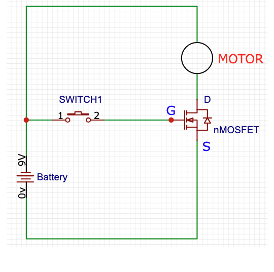

Task 15: Seven Segment LED (Bonus Task)
A seven-segment display is a form of electronic display device for displaying decimal numerals. It consists of seven LEDs arranged in a specific pattern that can display numbers 0-9 and some letters.
Each segment is a separate LED that can be controlled independently. By lighting up different combinations of segments, you can display different numbers and characters. A seven-segment LED can be either common anode or common cathode. This is important because it determines which side of the LED needs a resistor.
Additional Resources:
- DigiKey - How to Interface a Seven Segment Display with an Arduino (Comprehensive guide)
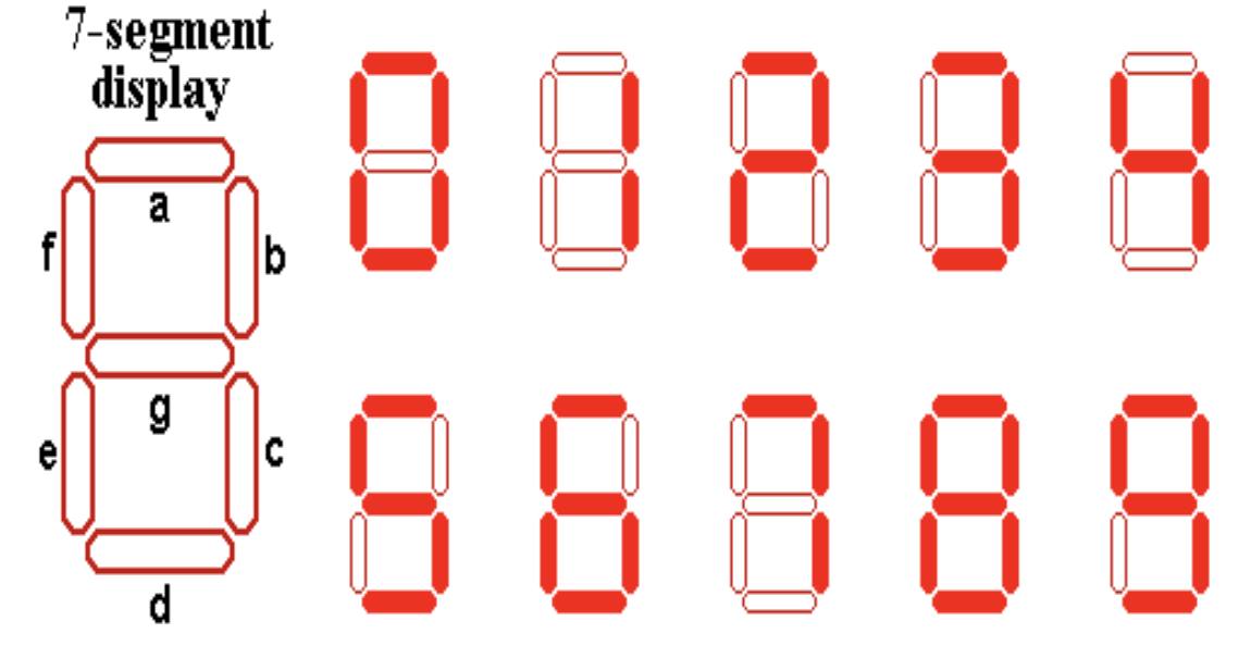
Task 16: RGB LED (Bonus Task)
An RGB LED (Red-Green-Blue Light Emitting Diode) is a special type of LED that contains three separate LEDs in one package: one red, one green, and one blue. By controlling the intensity of each color, you can create millions of different colors.
RGB LEDs can be either common anode or common cathode. In a common cathode RGB LED, all three color LEDs share a common cathode (negative terminal), and each color has its own anode (positive terminal). In a common anode RGB LED, all three colors share a common anode (positive terminal), and each color has its own cathode (negative terminal).
Identifying the LED type: In a common anode RGB LED, the common anode (positive) is usually the longest pin, but this should be verified. In a common cathode RGB LED, the rule does not always hold true. Always check the datasheet or use a multimeter to identify the pin configuration.
Task: Connect an RGB LED to your breadboard. Use appropriate current-limiting resistors for each color channel. Experiment with different combinations of colors by connecting different color channels to power. Try to create different colors by mixing red, green, and blue in various combinations.
Note: If you are using a 9V battery, it is recommended to start with a resistor value above 400Ω.
Additional Resources:
- DigiKey - How to Drive Multicolor LEDs (Comprehensive guide)
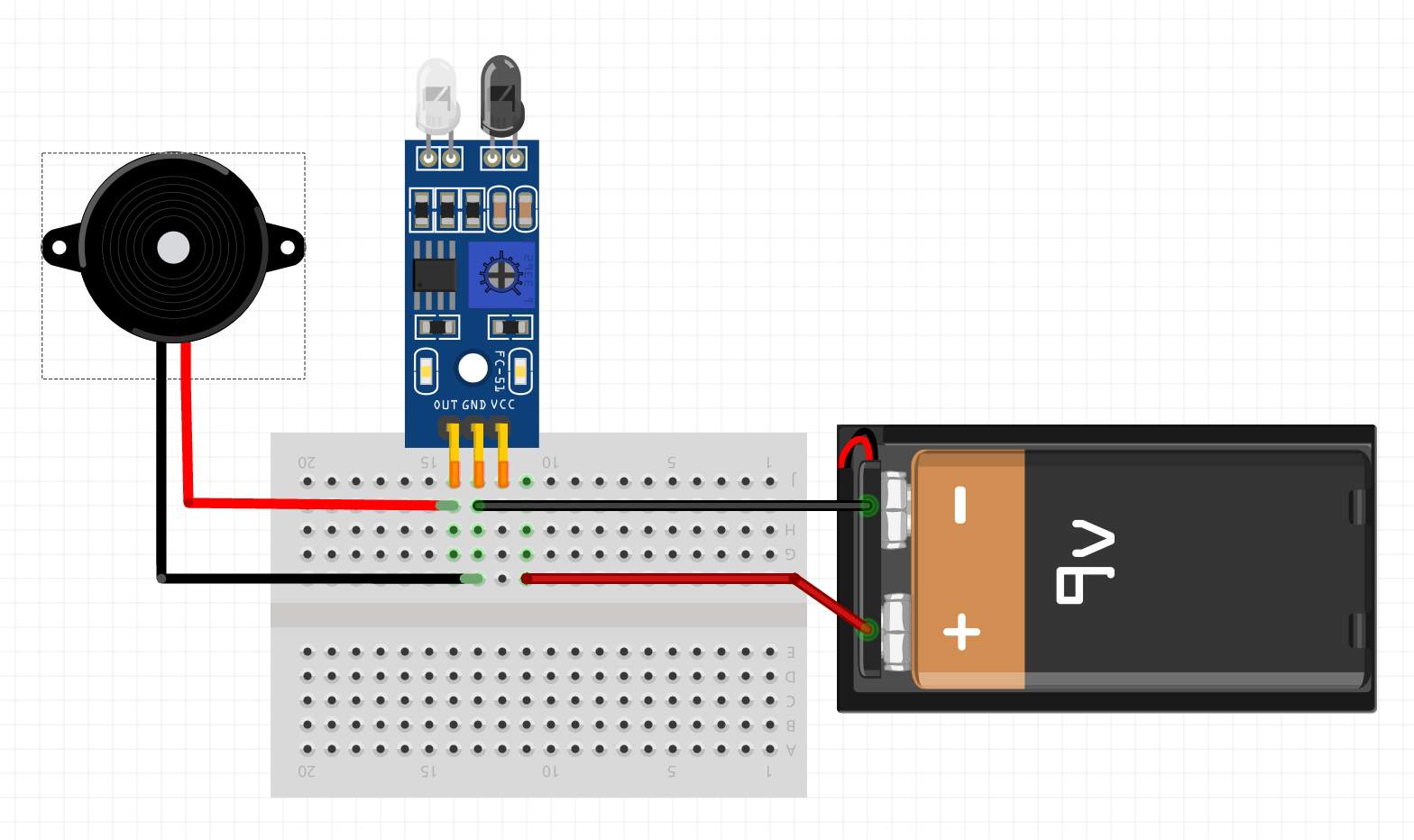
Task 17: Buzzer - Line Follower
For this task, you will need a small screwdriver and a dark line.
Place the sensor over the line and adjust it with the screwdriver so that the sensor reacts to the difference between dark and light.
Also test if you can adjust the line follower to follow the line.

Task 18: Soldering
For soldering practice, you will need a soldering iron and solder. In this context, it is sufficient to familiarize yourself with a few videos.
YouTube Videos
Task 19: What is Pull-up Resistor?
For future - good to know extra
Task: Find out what a pull-up resistor is and what it can be used for. Hint: digital data transmission and, for example, 1-wire devices. This will be needed later with Arduino.
Hint: Circuit Basics - Pull-up and Pull-down Resistors